


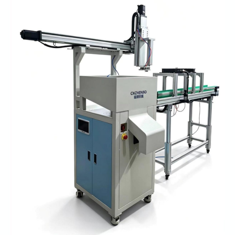
Ultrasonic Degating Machine
- Category: Products Center
- Phone: Mr Ordway
- Fax: +86-577-61517750
- Skype: alexlee2696@hotmail.com
- E-mail: info.2@mp-sonic.com
Ultrasonic Degating Machine
Fully Automatic Gate Separation Solution for Injection-Molded Parts
After an injection-molded part is formed, the part and the runner scrap remain connected. Getting this one step right on the production line is not easy: manual gate trimming is inefficient and inconsistent, and it can easily damage the cosmetic surface; a dedicated trimming die requires a separate investment, and a new die is needed every time the product changes.
The MP Sonic ultrasonic degating machine works by applying localized high-frequency vibration to the gate using ultrasonic oscillating energy. The plastic at the gate heats up and softens instantly, then breaks off cleanly — leaving a smooth break surface with no burrs or stringing. Combined with a two-axis servo robot for automatic loading and unloading, a production line needs only minimal supervision.
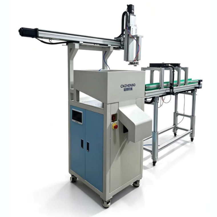
Fig. 1 | Ultrasonic degating machine (complete unit): main unit and control cabinet on the left, conveyor system on the right
1. What Is Ultrasonic Degating?
Ultrasonic degating is a precision post-process that uses ultrasonic oscillating energy to separate the injection-molded part from the scrap formed by the runner system. In the industry, it is also called ultrasonic separating, gate breaking, or gate vibration-off.
Here is how it works: the ultrasonic system focuses energy on the gate point of the injection runner and operates at 15 kHz or higher. The plastic at the gate is heated and melted by this high-frequency vibration, and the gate then breaks off cleanly, separating the part from the runner scrap.
Compared with traditional degating methods, ultrasonic degating delivers higher efficiency and a cleaner, smoother break.
2. Designing the Gate for a Clean Break
This is the most critical prerequisite for getting ultrasonic degating right — the gate design itself directly determines break quality. The technical documentation gives three explicit requirements:
• Keep the gate size at approximately 0.080 in (2.03 mm)
• Keep the gate area smooth
• Localize the melt zone
With proper design, the ultrasonic energy is concentrated on the gate and the melt zone stays controlled, producing a clean break. With poor design, the energy disperses and the melt zone overflows, resulting in uneven breaks, stringing, or even damage to the part itself.
Our recommendation: specify the gate requirements for ultrasonic degating at the mold design stage — it is far easier than tuning parameters on the production line after the mold has already been built.
3. Machine Structure: Six Systems
The complete machine consists of six systems, each performing its own role:
|
System |
Function |
|
Robotic arm system |
Automatically picks and feeds parts, completing loading and unloading |
|
Ultrasonic oscillation system |
Core working unit that applies ultrasonic energy to the gate |
|
Pneumatic gripper |
Grips and holds the part to keep it stable during degating |
|
Output port |
Output channel for degated parts |
|
Fan |
Aids heat dissipation for continuous, stable operation |
|
Conveyor system |
Conveys and sorts parts |
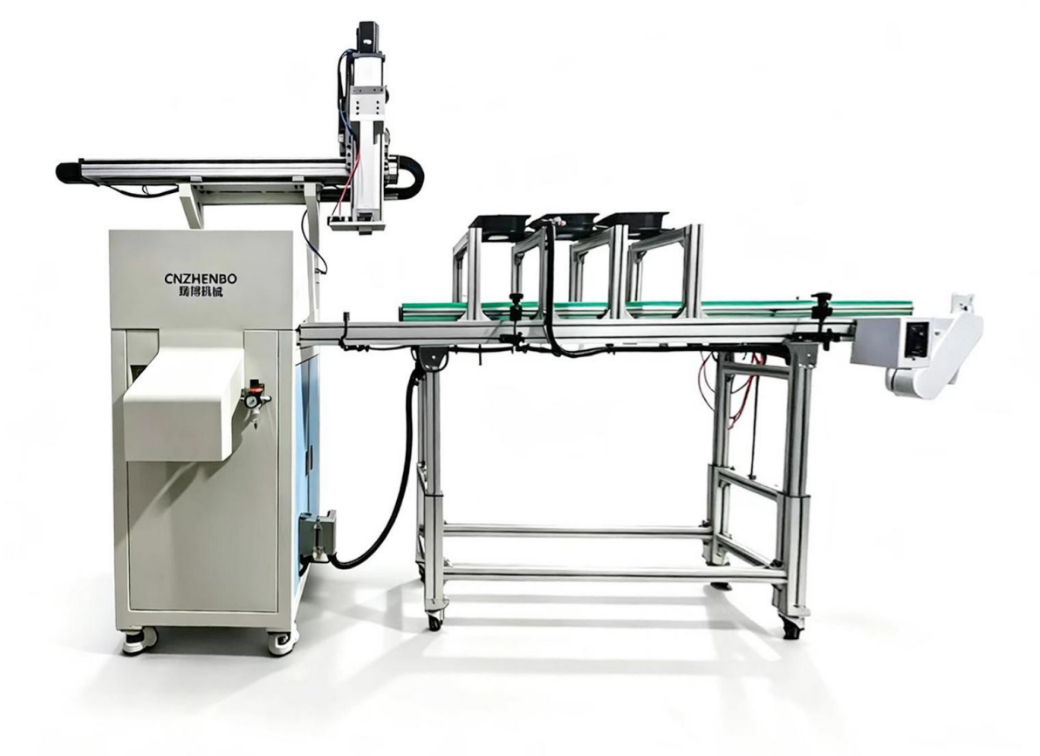
Fig. 2 | Overall layout of the main unit and conveyor line: the robot spans above the conveyor to pick and place parts
4. Key Components in Detail
4.1 Two-Axis Servo Robot
Handles part loading, unloading, and feeding, with the following features:
• High motion accuracy
• Adjustable stroke
• Fast motion speed
• Configurable speed and pressure
• Pneumatic gripper for loading and unloading
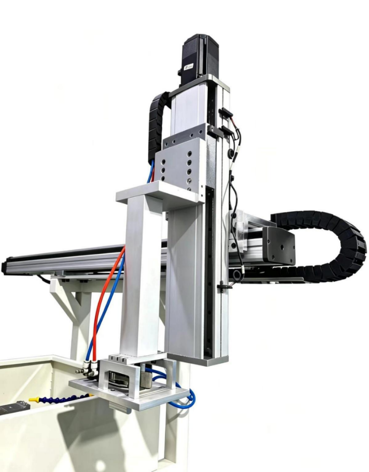
Fig. 3 | Two-axis servo robot: servo-driven, with configurable motion speed and pressure
4.2 Conveyor System
• Adjustable conveyor speed
• Sensor-controlled start/stop for loading positioning
• Adjustable channel width to fit parts of different sizes
• Built-in cooling channel for continuous production efficiency
4.3 Pneumatic Gripper and Ultrasonic Tooling
The part is gripped and held by the pneumatic gripper; the ultrasonic tooling (ultrasonic horn) is custom-designed to the part's injection molding design, and the horn material can be aluminum, steel, or titanium alloy.
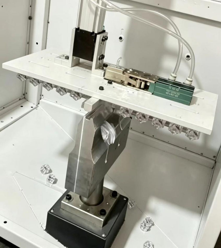
Fig. 4 | Pneumatic gripper and ultrasonic tooling: the part is held by the gripper, and the horn is custom-made to the part's injection molding design
4.4 Ultrasonic System
It consists of three parts — the ultrasonic horn, the generator, and the converter — operating at a working frequency of 15 kHz.
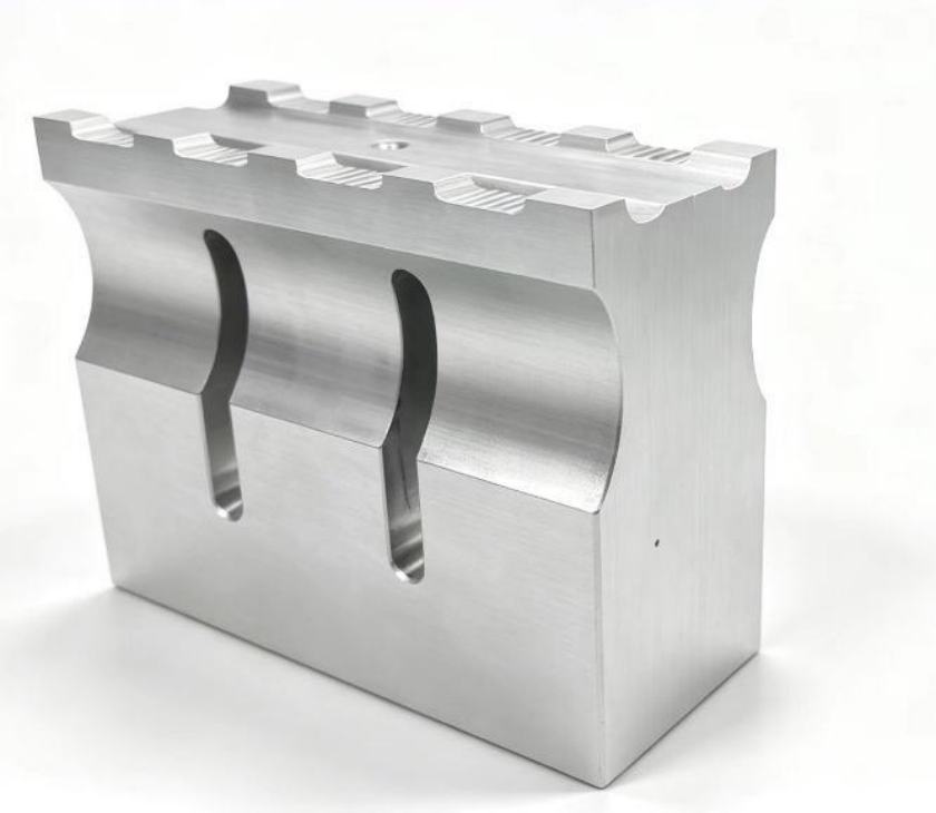
Fig. 5 | Ultrasonic horn: custom-designed to the gate layout, available in aluminum, steel, or titanium alloy
5. Machine Technical Specifications
|
Item |
Specification |
|
Model |
MPZ-E1526-R2S-CV1.5 |
|
Power supply |
220 V, single-phase, AC, 50/60 Hz |
|
Air supply |
0.5 MPa |
|
Ultrasonic frequency |
15 kHz |
|
Ultrasonic power |
2600 W |
|
Maximum power consumption |
6 kW |
|
Robot system |
Two-axis servo drive |
6. Core Advantages
• Cost-effective equipment: simplified structure, low entry investment
• Clean, neat breaks: localized ultrasonic melting, no burrs or stringing
• High efficiency: automated continuous operation with stable cycle time
• Stable operation: reliable performance for long-term mass production
• Fully automatic operation: robot handles loading and unloading, reducing line labor
7. Suitable Applications
• High-volume injection molding where gate finishing takes up significant labor
• Cosmetic parts that cannot tolerate burrs, white marks, or scratches from gate trimming
• Multi-product changeovers without wanting a dedicated trimming die for each product
• Wanting to reduce line labor and improve break consistency
8. FAQ
Q1: What ensures break quality?
Two factors: first, the gate design (gate size of about 2.03 mm, smooth gate area, and localized melt zone); second, the ultrasonic horn custom-made to the part's injection molding design. These two determine whether the energy can be concentrated on the gate.
Q2: What needs to change when switching products?
The ultrasonic horn is custom-designed to the part's injection molding design, so different products require a matching configuration; the conveyor channel width is adjustable to fit parts of different sizes.
Q3: How is loading and unloading carried out?
It is fully automated by the two-axis servo robot with a pneumatic gripper; motion stroke, speed, and pressure are all configurable.
Q4: What are the on-site requirements?
Only a 220 V single-phase power supply and a 0.5 MPa air supply are needed; the machine's maximum power consumption is 6 kW.
Q5: Can we verify suitability for our products first?
We recommend providing sample parts and gate design drawings for evaluation — the effectiveness of ultrasonic degating is directly related to the gate size and layout, and an accurate assessment requires seeing the actual part.